In this post, I’m going to show you about my CAN module and short explanation about what is CAN, and problem solved by CAN. Now let’s start with the problem which lead to the invention of CAN.
Problem of Automobile’s development
A long time a go, in the automobile industry, people start to make smarter cars with more and more features. A long with that, the car must contain more electrical components, that lead to the result that there are more and more wires in the car to connect these electrical components together. The more wire, the more complicated structure, the harder for the worker to detect and repair the car if there are any problems.
To fix this problem, in 1983, a company named Bosch started to develop CAN bus. Which allow an easier communication protocol between electrical components.
What is CAN bus?
A Controller Area Network (CAN bus) is a robust vehicle bus standard designed to allow microcontrollers and devices to communicate with each other’s applications without a host computer. It is a message-based protocol, designed originally to multiplex electrical wiring within automobiles to save on copper, but it can also be used in many other contexts. For each device, the date in a frame is transmitted serially but in such a way that if more than one device transmits at the same time, the highest priority device can continue while the other back off. Frames are received by all devices, including by the transmitting device.
Versions of CAN bus
| Name | Description |
|---|---|
| CAN 2.0A | Use 11 bits for identifier, smaller amount of nodes in bus |
| CAN 2.0B | Use 29 bits for identifier, bigger amount of nodes in bus |
| CANFD | Use different frame format, allows different data length, compatible with CAN 2.0 |
Applications of CAN bus
- Passenger vehicles, trucks, buses (combustion vehicles and electric vehicles)
- Agricultural equipment
- Electronic equipment for aviation and navigation
- Industrial automation and mechanical control
- Elevators, escalators
- Building automation
- Medical instruments and equipment
- Pedelecs
- Model railways/railroads
- Ships and other maritime applications
- Lighting control systems
- 3D Printers
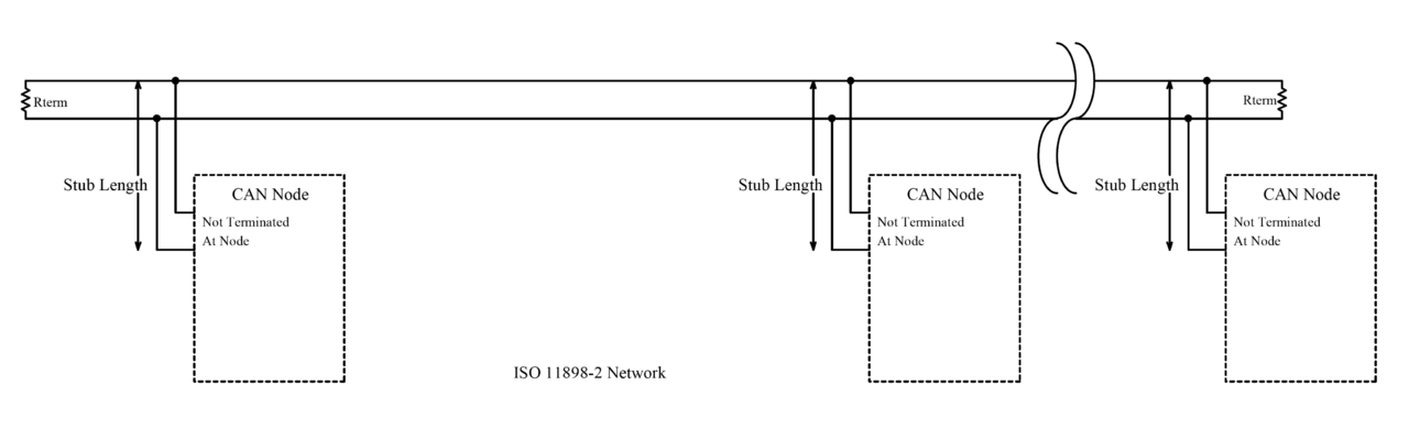
Physical organization of CAN bus
- CAN is a multi-master serial bus standard for connecting electronic control unit (ECUs) also known as nodes.
- Two or more nodes required on the CAN network to communicate.
- All nodes are connected to each other through a physically conventional two wire bus.
- The wires are a twisted pair with a 120 $\Omega$ which match with the characteristic impedance of the transmission line to avoid reflection.
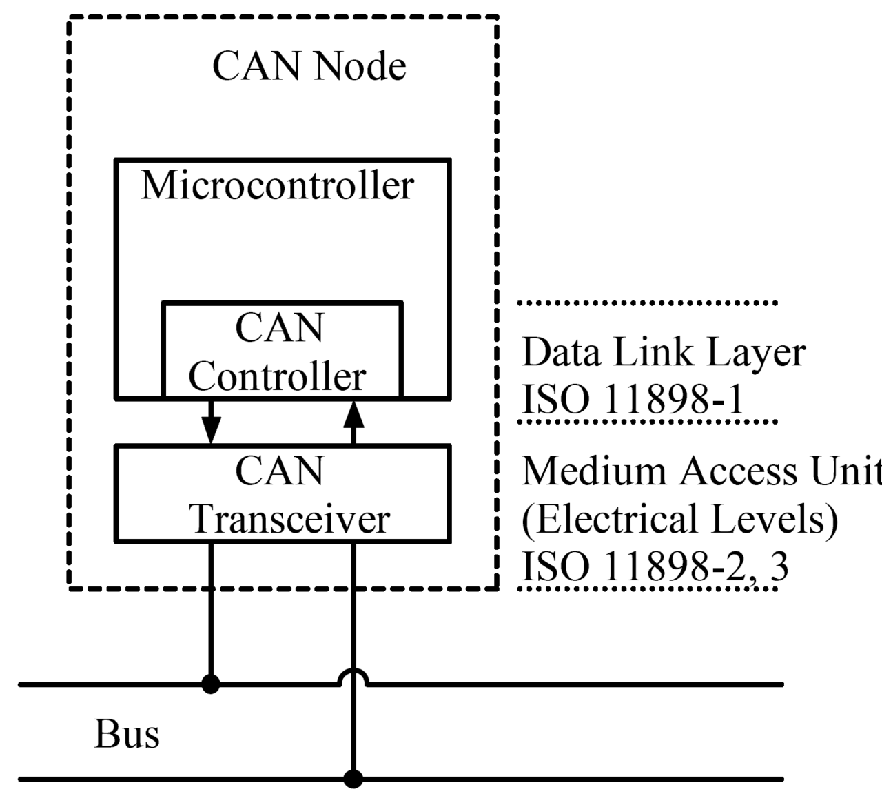
A CAN Node consists of:
- CAN Controller
- CAN Transceiver
- Microcontroller
Some microcontrollers like ESP32, STM32xxx have a built-in CAN Controller, so we just need to have additionally a CAN Transceiver to complete the node. But in some microcontroller like Arduino UNO R3 don’t have a built-in CAN Controller, to complete the CAN node, we have to add external CAN Controller and CAN Transceiver.
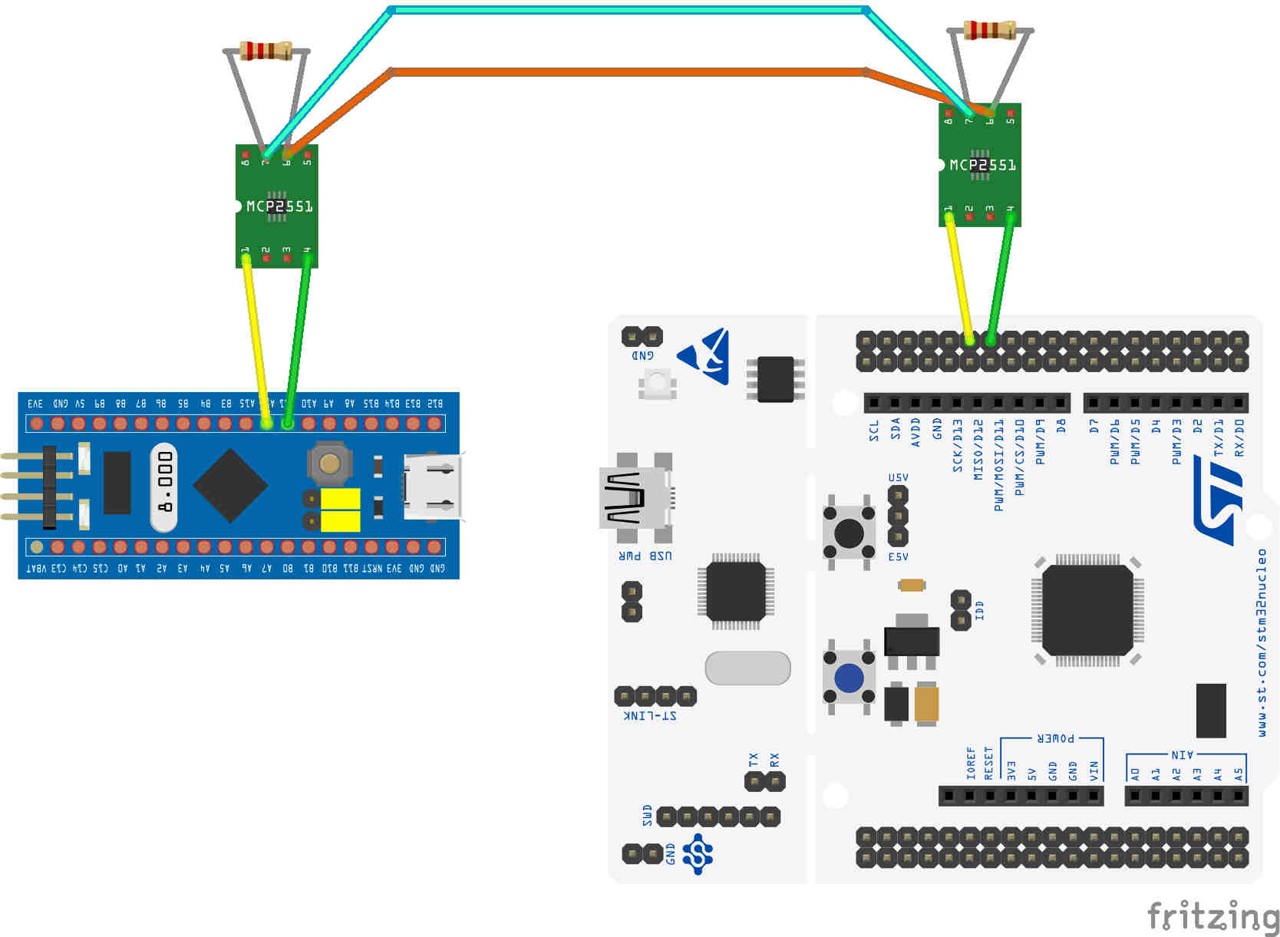
Because STM32 have built-in CAN Controller, so we only need to connect them via CAN Transceiver.
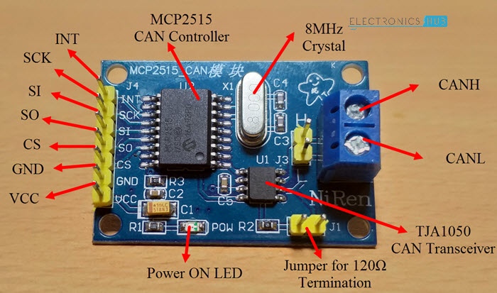
We use this module for connecting the Arduino UNO R3 because it doesn’t have the built-in CAN Controller. This module connects with the Arduino Uni via SPI connection.
Name of the components:
- CAN Controller:
MCP2515 - CAN Transceiver:
TJA1050
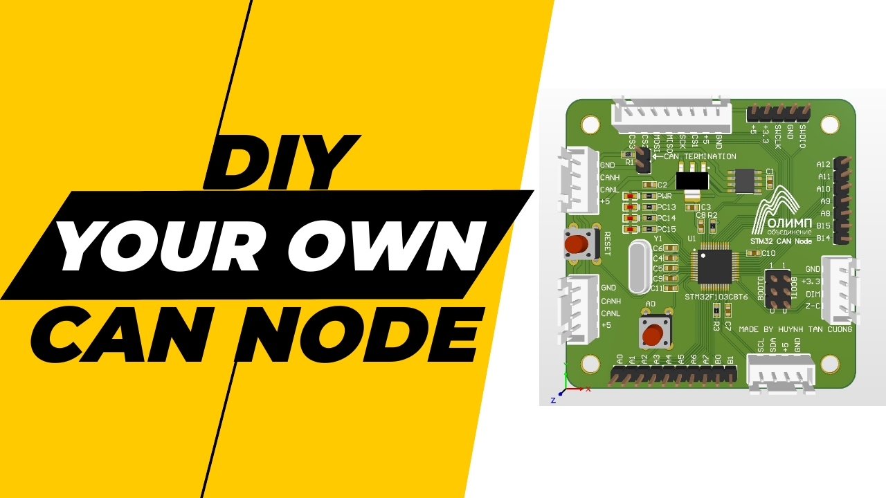
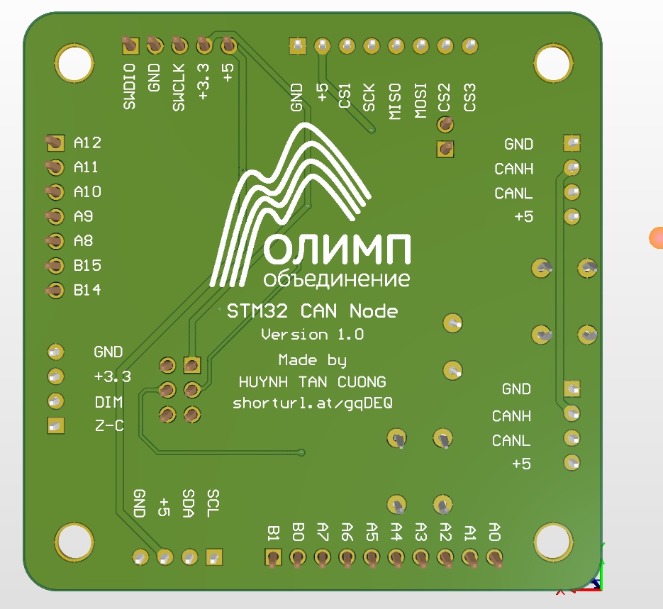
Design my own STM32 CAN Node
If we use a separate CAN Transceiver with the STM32 board. The complexity of wiring become bigger when we have lots of nodes to connect to the bus. To solve this problem, I decided to make a custom PCB board which have a CAN Transceiver lies on it.
Components
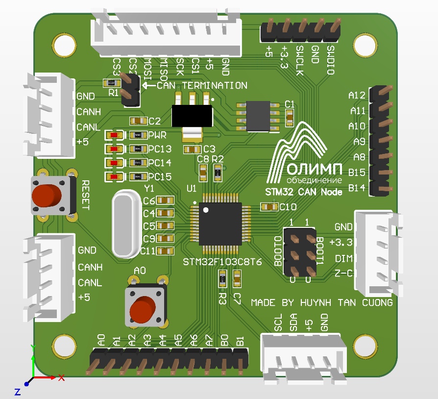
My custom CAN Node includes:
- Microcontroller
STM32F103C8T6 - CAN Transceiver
TJA1050 - I2C Connector
- SPI Connector
- 2x CAN Connector
- Headers for GPIO
- Boot configuration selector
- Connector for the thyristor control board
Connection between boards
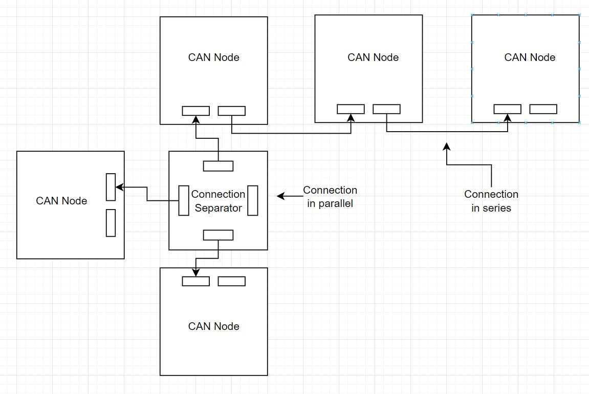
With 2x CAN Connector for each board, we can set up the boards connected in 2 ways:
- Connection in series
- Connection in parallel
A task for the future: we design this
Connection Separatorboard.
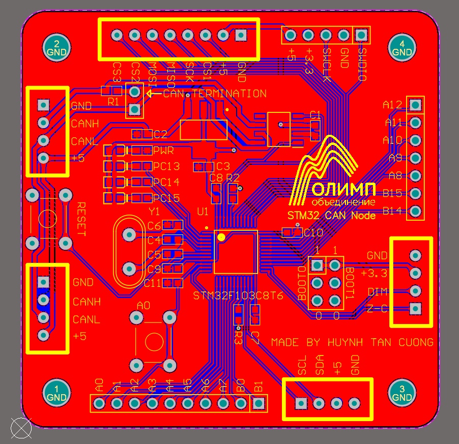
Access the file
You can access the repository for the designed file HERE
To design this board, I used Altium Designer program. You have to buy a license or use crack version to use it. I will consider to use KiCAD in the future, because it’s a free and open source program.